


Design Standards and Drainage Details for Wisconsin Curbs and Gutters
Design standards for concrete curb, gutter, and curb and gutter elements used on Wisconsin roadway projects are established to promote consistent construction practices across state and municipal work.
Requirements address geometry, material properties, jointing, and drainage coordination to support long-term pavement performance and roadway safety.
The application includes new construction, reconstruction, and rehabilitation projects that require defined edge restraint and controlled surface drainage.
Proper design and detailing limit pavement edge deterioration, reduce standing water, and improve vehicular and pedestrian safety.
Coordination with stormwater systems is required to maintain continuous flow along pavement edges and into collection structures.
Applicable Standards and References
Established standards govern the design and construction of curb and gutter systems on Wisconsin roadway projects.
Statewide detail drawings define geometry, reinforcement, and pavement interface requirements. Local standards supplement these provisions to address municipal practices and site-specific conditions.
Wisconsin DOT Standard Detail Drawings
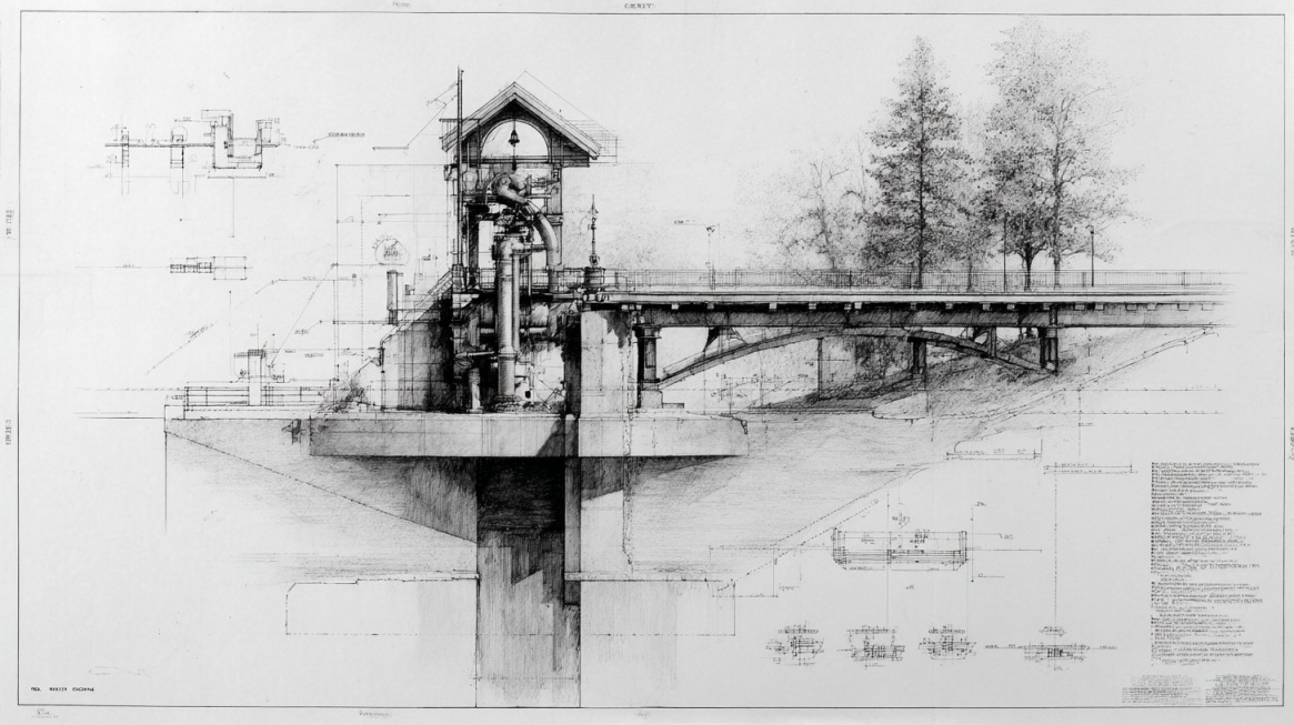
Wisconsin DOT Standard Detail Drawings in Series 08 define curb and gutter configurations, surface drainage components, and related construction details used statewide.
Drawings present dimensional requirements, reinforcement placement, joint spacing, and interface conditions with adjacent pavement systems to maintain consistency in public infrastructure.
- Standardized curb face heights and gutter widths
- Required gutter thickness and pavement tie conditions
- Joint spacing limits for contraction and construction joints
- Reinforcement and tie bar placement requirements
- Transitions at pavement edges and structural interfaces
SDD 08D01 covers concrete curb, concrete curb and gutter, and tie details.
Information includes curb type designations, dimensional geometry, base requirements, joint layout, and tie bar placement.
Geometry for each curb type is defined through measured face heights, back-of-curb widths, and gutter slopes to ensure uniform construction.
SDD 08D16 addresses concrete gutter, curb and gutter, and pavement tie details.
Minimum pavement thickness, tie bar spacing, and pavement interface conditions are defined to maintain structural continuity between the curb and adjacent pavement.
Pavement thickness and allowable panel widths are coordinated to reduce cracking and maintain load transfer.
- Minimum concrete pavement thickness adjacent to curb and gutter
- Tie bar size and spacing, typically No. 4 bars at two feet zero inches in length spaced three feet zero inches center to center
- Maximum panel width based on slab thickness
- Longitudinal joint placement criteria when panel width exceeds allowable limits
Local Engineering Standard Details
Municipal engineering standards supplement statewide requirements and provide additional drafting and construction direction.
Local standards guide plan preparation, curb return geometry at intersections, and integration with sidewalk and driveway features.
Project-specific modifications may be necessary due to existing utilities, constrained right of way, or drainage limitations.
During construction, consultation with local concrete contractors can help ensure proper implementation of curb, gutter, and pavement standards while maintaining quality and compliance with project specifications.
Any deviation must remain consistent with statewide structural and drainage criteria to preserve system performance.
Coordination between municipal and state requirements is required during plan development to avoid conflicts in geometry or material specifications.
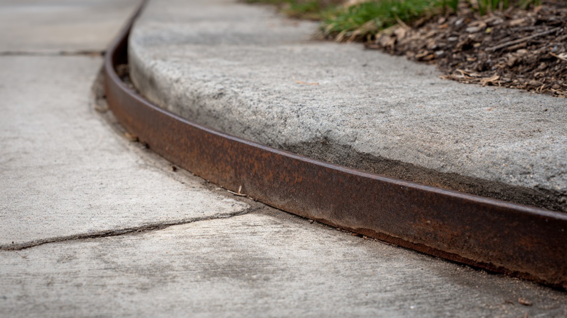
Curb and Gutter Types and Geometry
Curb and gutter geometry defines roadway edge control, drainage direction, and pavement support.
Proper selection of curb type and dimensional configuration ensures compatibility with roadway classification, traffic loading, and adjacent features.
Concrete Curb and Gutter Types
Standard curb and gutter profiles are designated by letter codes including A, D, G, J, K, L, R, T, TBT, and TBTT.
Selection depends on roadway classification, adjacent features, and drainage needs.
Functional applications vary by curb designation.
- Type R and Type T at roundabouts and circulatory roadways
- Type TBT and Type TBTT at thrie beam transitions to manage runoff near guardrail systems
- Types A, G, K, and R, where structural tie bars are required for pavement connection
Reverse slope gutter sections are used at locations where flowline elevation must match storm inlet or surface drain elevations.
Reverse slope conditions are clearly identified in plan sheets to maintain positive drainage toward designated low points.
Profile adjustments must be gradual to avoid abrupt grade changes that could disrupt vehicle movement or water flow.
Dimensional Standards
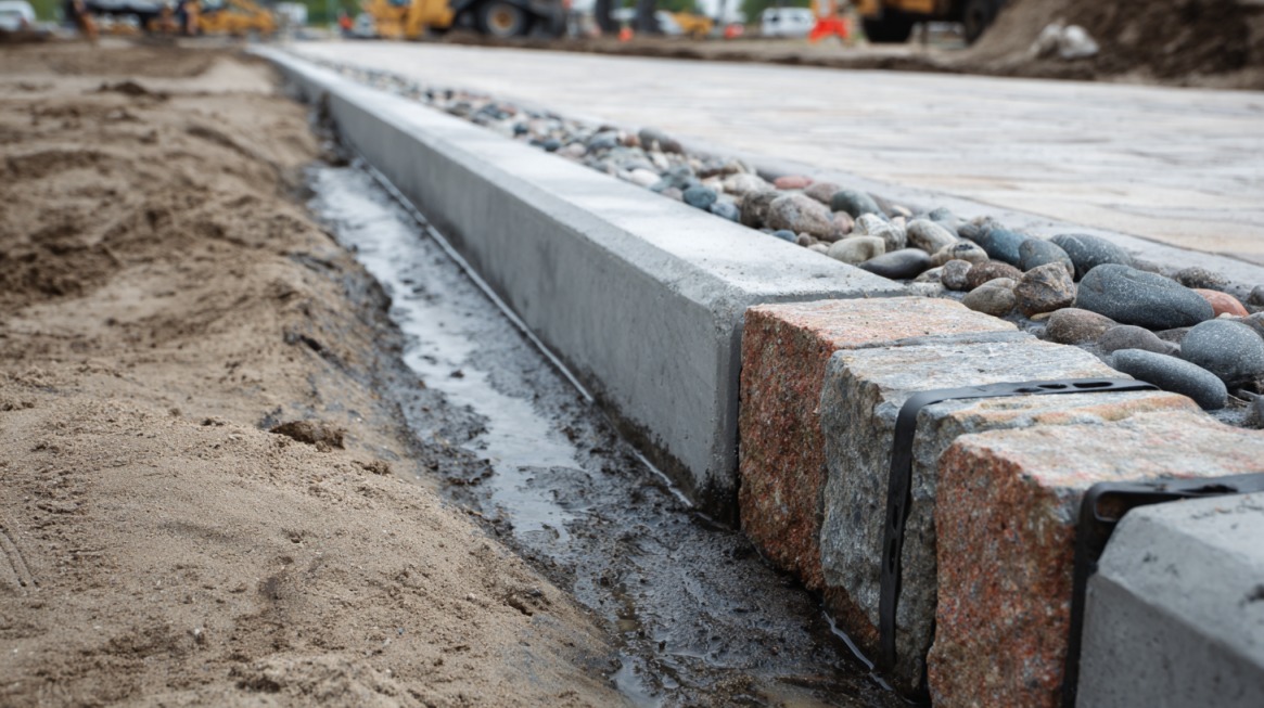
Dimensional criteria control structural capacity and drainage performance. Curb geometry follows established measurements to maintain consistency in field layout and construction.
Typical face of curb is set six inches from the back of the curb for staking and layout unless noted otherwise in project plans. This offset provides a reference point for alignment control during construction.
Gutter thickness requirements vary by loading condition.
- Six inches under general roadway conditions
- Eight inches when adjacent to concrete truck aprons located behind curb sections
Increased thickness adjacent to truck aprons provides additional resistance to heavy wheel loads and reduces cracking potential.
Standard gutter cross slope is four percent unless modified by plan note or special detail. Cross slope directs runoff toward the flowline and into inlet structures without creating ponding.
Longitudinal grade must be coordinated with cross slope to ensure continuous drainage along the curb line.
Maximum concrete pavement panel width depends on pavement thickness.
- Panels less than ten inches thick limited to twelve feet in width
- Thicker pavement sections permitting panel widths up to fifteen feet in accordance with tabulated limits
Panel width control reduces uncontrolled cracking and supports long-term pavement performance.
Materials and Tie Details
Material selection and tie detailing contribute to structural continuity between curb and pavement.
- Mix design
- Curing
- Placement
- Workmanship
Mix properties must provide durability under freeze thaw cycles and exposure to deicing chemicals.
All pavement ties and tie bars are epoxy coated in accordance with Subsection 505.2.6.2 to reduce corrosion potential.
Typical tie bars consist of No. 4 bars with a length of two feet zero inches spaced three feet zero inches center to center.
Epoxy coating protects reinforcement in environments subject to moisture and chlorides.
Tie bars are required for curb and gutter types A, G, K, R, and TBTT to ensure structural connection between curb sections and adjacent pavement.
Proper embedment depth and alignment are necessary to control differential movement and maintain edge support.
Drainage Integration with Curb and Gutter
Effective drainage integration ensures that curb and gutter systems function as part of the overall stormwater management network.
Geometry, slope, and inlet coordination must be designed as a continuous system rather than isolated elements.
Drainage Flow Principles
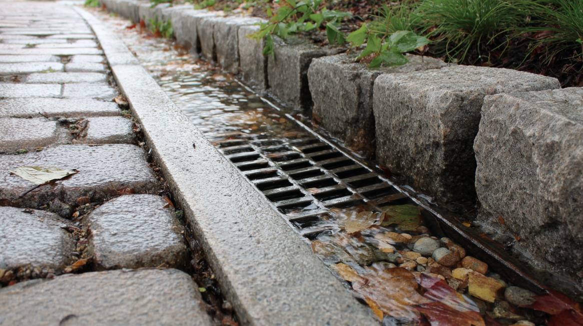
Curb and gutter systems convey storm runoff longitudinally along pavement edges.
Gutter cross slope and longitudinal grade direct water toward designated inlets and surface drains.
Continuous flow reduces surface ponding and protects pavement edges against erosion.
- Maintaining positive longitudinal grade along the flowline
- Avoiding flat sections that allow sediment accumulation
- Coordinating curb elevations with roadway profile grades
Adequate slope must be maintained along the flowline to prevent localized flooding. Design elevations are coordinated with roadway profile grades to sustain uninterrupted drainage paths.
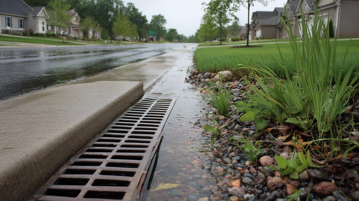
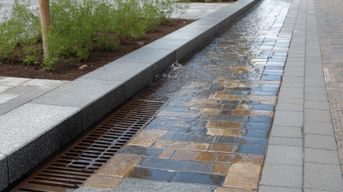
Inlet and Surface Drain Interface
Interface between gutter and inlet structures must be carefully detailed to maximize hydraulic efficiency.
Flowline elevations are depressed at inlet locations when required to match grate elevations and improve water capture.
Depressed sections are detailed in plan sheets to provide smooth transitions into drainage structures.
Reverse slope gutter sections are indicated when gutter grade must change direction to move water toward a low point inlet. Proper grading ensures that runoff does not bypass collection structures or accumulate upstream of inlets.
Transition lengths must be adequate to maintain constructability and ride quality.
Special Drainage Conditions
Complex roadway features require modified drainage detailing. Roundabout circulatory roadways may require reverse slope gutter applications to control internal drainage patterns.
Design must account for vehicle tracking paths, superelevation transitions, and entry and exit geometry.
Curb ramps, driveway tie ins, and pedestrian crossings require adjusted curb and gutter details to maintain consistent drainage flow.
Adjustments must preserve accessibility requirements while preventing water accumulation at transition points. Coordination among geometric design, drainage design, and accessibility criteria is required for successful implementation.
The Bottom Line
- Uniform geometry
- Reliable drainage flow
- Durable construction
Compliance with dimensional criteria, material requirements, and tie details supports long-term roadway performance.
Coordination between curb design and drainage detailing reduces surface water buildup and enhances overall roadway safety and service life.
Also Read: What are the best small towns in Wisconsin that you should visit this summer?